To optimize the control process of lighting fixtures in one or even two rooms, you can not use two different devices, but install one switch with two keys.
A scheme for connecting a two-gang switch, which demonstrates the sequence of connecting electromechanical devices and artificial light sources with wires connecting them to each other, will help to implement the plan.
The article shows the working diagrams of connecting the switch, lists tips on the distribution of wires, and also describes step-by-step instruction on installing a double switch. The information provided will be a great help to the home master who plans to perform all the work on his own.
Why choose two-key switches
There are two popular circuit solutions that have been used successfully for a long time when equipping a system of electrical equipment for private houses and apartments.
Option number 1. Installation of DV (two-gang switch) in the bathroom area, if the toilet and bathroom are separated by a wall. Thus, one key controls the light bulb in the toilet, the second - in the bathroom.
Today, this option remains relevant and is actively used in typical housing, where the wiring diagram has not fundamentally changed.
However, to expand the control capabilities, instead of the two-key model, a three-key switch is sometimes installed if it is supposed to control not one but two lamps or groups of lamps in the bathroom.

Installation of DV instead of two separate devices is preferable from the point of view of saving materials for installation. In addition, it is more convenient to use one switch: using the keys, you can turn the lights on and off in different rooms with one movement of your hand
Option number 2. The second common use of a two-key switch is chandelier control. The design of the lighting device makes it possible to connect the bulbs to two different keys, due to which the light level is adjusted.
If one key controls 2 light bulbs, and the second - 4, then you can use three lighting modes: muted (2), bright (4) and intense (6).

If bright lighting is required for reading, games or a family dinner, then turn on all the lights; in order to create a calm atmosphere for an evening rest, there is enough dim light from one lamp
A large number of modern chandeliers, especially with LEDs, are controlled from a remote control. Especially advanced in this direction are multi-colored multi-mode Chinese models. But the option with the switch is still more reliable - the remote control may fail, and electromechanics rarely fail.
With the DV, you can control not only one, but also two lighting devices (or groups) installed in one room. For example, if you connect a chandelier and a pair of sconces to different keys.
So, the functions of the two keys are very useful:
- control of multiple light sources;
- Segment control of one, but multi-track device (chandelier);
- the ability to adjust the degree of illumination in the room;
- saving mounting elements.
If you appreciated the capabilities of the two-key model and want to replace the old one-key with it, you will have to change the connection diagram and, most likely, you need to start with the wiring.
Connection schemes for dual models
Before starting the installation, it is necessary to divide the spotlights or lamps of the chandelier, which are planned to be connected to one DV, into two groups. To create different lighting modes, they must be unequal (for example, 2 + 6 or 1 + 2).
It is not possible to connect more than two groups to one two-keyboard, for this purpose a three-keyboard switch or separate electromechanical devices are used.

Using the simplest wiring diagram, you can correctly distribute the wires. But first you need to study the color and alphanumeric designations, so that in the future it is easier to "communicate" with schemes (+)
The obligatory elements of any DV connection scheme include the electrical device itself, the junction box and the circuit breaker, which are installed on the electrical panel.
Also, new wires will be required if the old ones do not meet modern standards - in the houses built in the middle of the 20th century, aluminum wires remained.
Image Gallery
Photo from
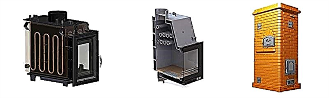
Overhead or internal two-gang switch
Junction box for connecting wires
Automatic lighting protection device
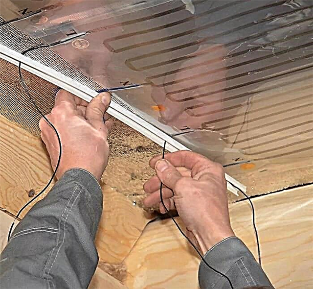
Wires to create an electrical circuit
One of the differences in the wiring diagrams relates to grounding systems. Old houses use the outdated TN-C system.
Its difference is that the ground and ground conductors are connected in one PEN wire, so only two wires pass from the machine to the apartment instead of three. With the TN-C grounding system, the wiring diagram looks like this.

Two wires are supplied from the switchboard: blue (zero) and red (phase). In the distribution box, the phase goes to the red wire of the switch, where it is mounted in a common terminal, and zero is immediately transferred to the light bulbs of the lighting device (one or several) (+)
If you need to connect a chandelier with several horns in the conditions of the TN-C system, then the scheme is as follows.

This load distribution increases the number of wires in the distribution box: 2 from the machine, 3 from the switch and 3 from the chandelier, that is, only 8 wires (+)
However, the scheme changes fundamentally if you should not connect a chandelier where all the lights are concentrated in one place, but connect two bulbs. Each lighting fixture requires a separately laid wire.

The working zero from the shield is divided into two groups of lamps, the phase still goes to the switch. From the switch, two phase wires are scattered along both groups of bulbs (+)
The modern TN-S grounding system does not require combining earth with zero, so three standard conductors are laid from the shield.

The distribution of the wires remains the same, but in the distribution box there is an increase in the number of connections, since the earth together with zero goes to the groups of lamps (+)
After ascertaining the type of the grounding system, it remains to choose a suitable circuit and transfer it to the circuit breaker installation drawing, while specifying the installation locations of all the devices involved.
When planning, remember that the installation height of electrical installations for private use according to the PUE is from 0.8 m to 1.7 m, the distance to the gas pipe is not less than 0.6 m, to the door jamb - at least 0.15-0.20 m.
Step-by-step DV installation guide
Before starting work, you must repeat the safety rules, purchase all the necessary devices and wires, and also prepare a tool for mounting devices and connecting wires.
A wall cutter, a drill and a punch will be required if it becomes necessary to lay new wiring. Work gloves, protective clothing and goggles (mask) will not be superfluous in the process of performing "dirty" work.
Installation of the protective device in the electrical panel
There is a possibility that a separate machine for one lighting group is already installed on the flap. But this is possible only if the house is new or recently undergone major repairs. Previously, it was not customary to integrate rosette and lighting groups into separate circuits.

Separate lighting lines for rooms provide more opportunities during the installation of new fixtures or in the process of repair work: you can completely turn off the lights in one room without affecting the rest of the rooms
We strongly recommend that you call a qualified electrician for installation of the machine, as independent manipulations with protective equipment in the shield are prohibited.
All work, further related to wiring, must be started precisely from the apartment-wide electric switchboard or cabinet, in particular, by turning off the machine of the circuit of interest (in our case, the lighting).
Wiring options: hidden and outdoor
In urban apartments and modern cottages, hidden wiring is used, as it gives more room for decoration, moreover, it is safely masked behind a layer of insulation in the wall.
In wooden houses, an open type of wiring is implemented, because laying wires inside the logs is complicated and costly - each cable must be placed inside a metal pipe.

For outdoor use, wires are produced in a special braid and accessories - ceramic rollers. Retro collections with rotary switches and twisted wires are especially popular.
To organize the electrical network in an ordinary apartment, it is necessary to groove the walls in all the junction boxes, sockets and switches.
Strobes, according to the PUE, must pass strictly horizontally (at a height of at least 2 m from the floor) or vertically.
Image Gallery
Photo from
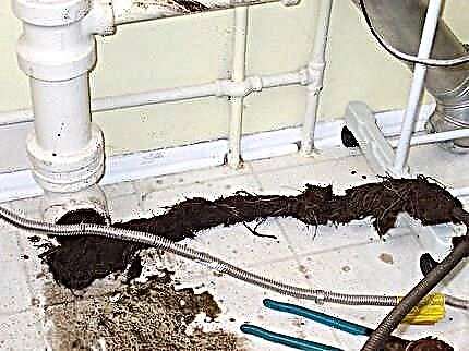
Wall chipping with a special tool
Preparing Grooves for Wires
Cutting holes for the switch
Mortar Strob mortar
At the same stage, we install the junction box and the socket, fixing with plaster. Strobing is the longest, most laborious and difficult stage.
After it, cleaning the premises is mandatory: it is necessary to take out the garbage, vacuum and mop the floor. Dust particles should not get into the switch box or inside the switch mechanism, that is, at the junction of the wires.
Connection of wires in the electrical box
The junction box is installed directly above the switch or in another place convenient for maintenance. It must not be hidden under the cladding on the wall, as intervention may be required at any time.
Image Gallery
Photo from
What wires lead into the box
Stripping and stripping
Wiring ready for connection
The simplest connection method is twisting wires
The photo shows how to twist the wires. This is the easiest, but not the safest, method of connecting wires. Now there are more advanced methods, for example, using terminal blocks - convenient self-clamping devices. Soldering and welding are extremely rare.
Switch connection and installation
For independent connection and installation of a two-gang switch, you will need screwdrivers, pliers, pliers, a knife, wire cutters, a level.
Hands should be protected with gloves for electrical work with a protective insulating layer. In addition, an indicator screwdriver or tester is useful.
Image Gallery
Photo from
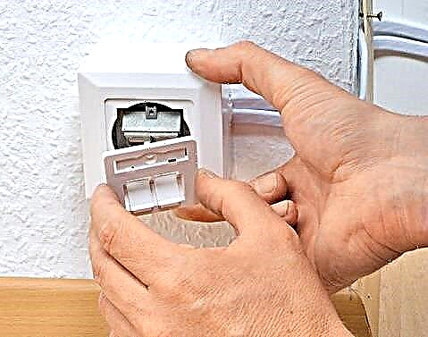
Step 1 - preparing a niche for installation
Step 2 - disassembling the switch
Step 3 - wire trimming
Step 4 - wire stripping
It was a kind of preparatory stage. After stripping the cores, you can begin to connect the wires to the switch.
Image Gallery
Photo from
The common phase conductor having a red or brown color of insulation is fixed in the terminal block according to the diagram. There are pointers on the back (e.g. L)
Standard switches use a screw type connection. That is, after the wire is inserted into the terminal, it must be clamped by tightening the screw
The remaining two wires lead to two luminaires or groups of lamps. These wires are connected to the terminals indicated by numbers or arrows.
After making sure that the wires are fixed correctly, according to the selected connection diagram, insert the mechanism into the socket or just fix it on the wall
Align the device with the horizontal axis. To do this, use the level, and adjust the position of the device using light movements
Usually the internal mechanism is mounted on a metal frame, which is screwed to the wall with 2-4 screws. Then check the position again
Lastly, the decorative outer part of the plastic parts is replaced - the frame is snapped and keys are inserted
An initial check must be carried out before installing the mechanism in the wall. At the final stage, another test is performed.
Step 5 - Connecting the Right Phase
Step 6 - Fixing Contacts
Step 7 - connecting the outgoing phases
Step 8 - mounting the mechanism in place
Step 9 - checking the horizontal position
Step 10 - Attaching the Switch
Step 11 - installation of the decorative part
Step 12 - testing the operation of the switch.
The models of switches and wires may be different, but the connection diagram remains the same. The connection in the distribution box can differ only by the addition of earth from the incoming power and the same grounding wires - from the lamps.
As you can see, there are a lot of works on installing the DV, and even if you just need to replace and reconnect the device, you can save money by doing everything yourself. Calling an electrician will cost from 200 to 500 rubles (the cost of only replacing the switch).
Safety Compliance
Electric shock can result in irreversible consequences, therefore, before each procedure for installing a switch or socket, a number of simple rules should be observed:
- the first step should always be to turn off the power on the switchboard - to protect and install machines;
- it should become a habit to regularly check the voltage with the help of a tester or indicator;
- only serviceable tools with insulated handles and high-quality, unworn materials should be used;
- Clothing and shoes should be comfortable and not cause discomfort during work.
When working with a chipper, circular saw, chipper, hammer or drill, it is advisable to additionally use a protective mask and a respirator.
Outsiders must be prohibited from entering the work area. If children live in the apartment or there are animals, it is better to leave them in another room for a while under the supervision of adults or send them to visit.
From the video materials presented below, you can learn how to independently connect a two-gang light switch, how to correctly connect the wires and make the installation of electrical devices.
How to connect wires to terminals:
Installation of the double block "switch + socket":
How does the chandelier connect to the DV:
Living in a modern house is impossible without the use of electrical appliances and devices, so the skills of "communication" with electricity can come in handy at any time.
Having learned the theory and practiced a little at home, you can easily change the switch, install a power outlet, or split the home power supply into several easy-to-use circuits.
Do you have any personal experience connecting a two-key switch? Want to share your knowledge or ask questions about the topic? Please leave comments and participate in discussions - the feedback form is located below.